The Georgia Tech Cryo Laboratory (GTCL) is a well-equipped computational simulation and experimental testing facility. Among GTCL equipment are a 500 W dual piston compressor, a 4.2 K Sumitomo cryocooler, and a fully instrumented 9 cubic feet dewar.
The computational facilities are similarly vast. GTCL owns more than 10 CPUs dedicated to cryogenics and thermal-science research. In addition, the research group has easy and virtually unlimited access to the Georgia Tech Library West Commons Productivity Cluster – a computer cluster equipped with 85 PC workstations and a multitude of other equipment; the Multimedia Studio –an area equipped with a multitude if workstations and a plethora of software; and most importantly, the Georgia Tech Institute for Data and High Performance Computing (IDH), and Partnership for an Advanced Computing Environment (PACE) which includes a community cluster of more than 1,500 CPUs. The Georgia Tech computer facilities are licensed to use for research purposes a vast array of software (Fluent, MATLAB, SolidWorks, Pro-E, ANSYS, AutoCAD, COMSOL-Multiphysics, MD NASTRAN). The GTCL has independent licenses to use Sage, ANSYS Fluent, and Thermal Desktop.
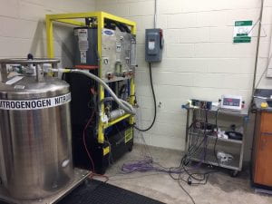
 An experimental set up for studying the hydrodynamics, phase change and heat transfer in the double helicoidally coiled heat exchanger has been developed. Schematic of prototypical fuel delivery system heat exchanger is shown. The system consists of two main lines: the fuel flow (shown in grey) and the coolant flow loop (shown in blue). The fuel in a prototype is LNG, however, for safety reasons LN2 is used in the experiments instead. The cylinder (for single phase flow experiments with gas) or dewar (for LN2 tests) F supplies the fuel. The cylinder/dewar is placed on a weighing scale, W, to calculate the average mass flow rate by measuring the slope of the curve representing the variation of the dewar’s weight against time. A vacuum jacket insulated hose connects the dewar to the inlet of the heat exchanger. A safety valve, V is placed in the fuel line, right before the fuel enters the heat exchanger. The fuel flows through the double helicoidally coiled tube of the heat exchanger, and from there into an analogous flowmeter, FF that reports the volumetric flow. This analogous flow meter provides an approximate on-line mass flow rate during the experiments. Upon leaving the test section, the fuel is discharged into the surroundings.
On the secondary side a large reservoir, R, contains a 50:50 mixture by volume of monoethylene glycol and water. A pump (AMT 2853-95), P, is used to pump the coolant in the outer shell of the heat exchanger. The coolant mixture is heated to about 180 F (82.2oC) in the reservoir and is then pumped into the secondary side (outer shell) of the heat exchanger. A bypass valve controls the coolant flow rate. A flowmeter, FC, measures the coolant flow line. The coolant exiting the heat exchanger shell is recycled back into the reservoir. Thermocouples and pressure sensors are placed at the inlet and outlet of the helical coils and outer shell of the heat exchanger. The outer shell is covered by two layers of insulation. The experimental set up is equipped with an oxygen sensor to monitor O2 levels since N2 gas is being released continuously.
The helicoidally coiled tube is made of 301 Stainless Steel and have horizontal axes.

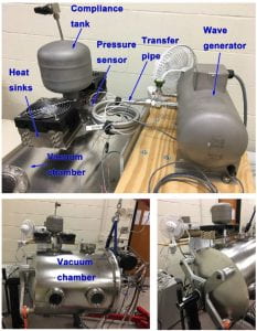
 This is the test section for testing the performance of cyrocooler. The vacuum chamber and the mounted cryocooler can be tilted up to 180 degree. The vacuum chamber can be rotated around its axis from vertical position (0°, expecting no cooling deterioration caused by gravity), as shown in lower two figures, to cold end oriented up (180°). The Pulse Tube Cryocooler (PTC) was driven by a 60 Hz wave generator. The cold tip was sealed inside the vacuum chamber and covered by a radiation shield to minimize convective and radiative loss between the cold tip and the environment. A machined copper test plate was attached to the cold end of the cold tip. Two 25 W heaters were installed in the through holes of the test plate to provide the cooling load for the PTC. A LakeShore DT-670D silicon diode cryogenic temperature sensor was also installed in the test plate to measure the cold end temperature. A Cryo-con Model 24C temperature controller was used to control the power of the heater automatically. The warm heat exchanger (WHX) was exposed to the laboratory air and cooled by two heat sinks. A T-type thermocouple was attached to the WHX to measure the surface temperature of the WHX.
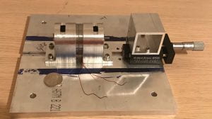
This section relates to equipment for testing the high frequency low volume compressor motor which is used for miniature space qualified Stirling cryocooler. The motor is built, assembled and tested at Georgia Tech Cryo Lab. Some of the main equipment for testing the motor depicted below include: Function generator, load cell model Futek 370005, Laser vibrometer model Polytec OFV3001 for measuring stroke and velocity of the shaft, digital oscilloscope, strobe light, stereo amplifier, and current probe.


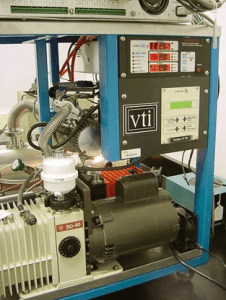
GT Cryo Lab 4 K Dewar Test Apparatus.

- Wave generator at the top of the Dewar (left section).
- Sumitomo GM cryocooler (120K – 4 K; 1 W at 4 K) on top of the Dewar (middle section).
- Vacuum pump (cart)
- 9 ft3vacuum space (27 inch diameter).
- 360° single axis rotation capability.
.


